We are part of —
 🔍
 🔍
 🔍
 🔍
 🔍
 🔍
 🔍
 🔍
IDS RIS Hi-Pave GPR for road and airport pavement assessment
Price on request
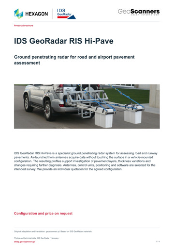
IDS GeoRadar RIS Hi-Pave is a specialist ground penetrating radar system for assessing road and runway pavements. Air-launched horn antennas acquire data without touching the surface in a vehicle-mounted configuration. The resulting profiles support investigation of pavement layers, thickness variations and changes requiring further diagnosis. Antennas, control units, positioning and software are selected for the intended survey. We provide an individual quotation for the agreed configuration.
Ready to buy this product?
Why choose us?
- Over a decade of experience
- Professional training
- We work throughout the EU
- Professional after-sales support
- We offer premium products
IDS GeoRadar / Hexagon
See how the pavement changes along the route
IDS GeoRadar RIS Hi-Pave is a specialist ground penetrating radar system for assessing road and runway pavements. Air-launched horn antennas acquire data without touching the surface in a vehicle-mounted configuration. The resulting profiles support investigation of pavement layers, thickness variations and changes requiring further diagnosis. Antennas, control units, positioning and software are selected for the intended survey. We provide an individual quotation for the agreed configuration.
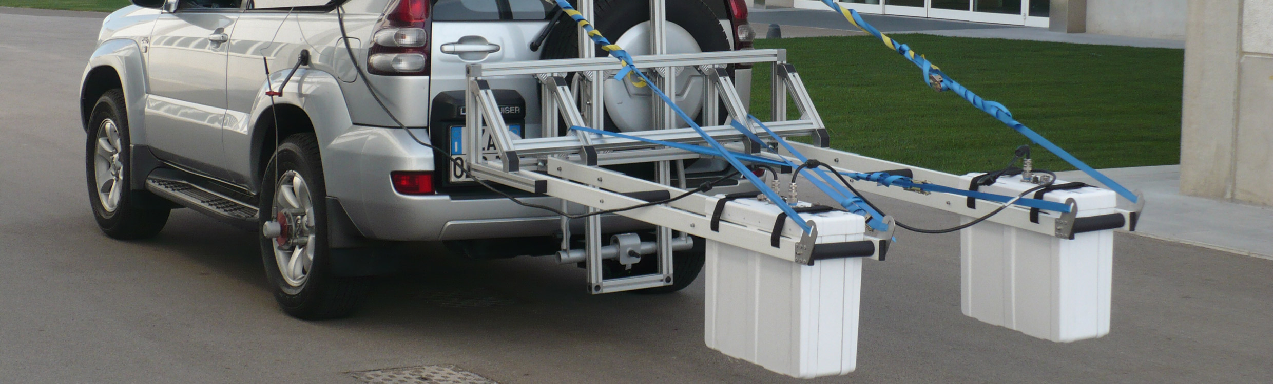
Road and airport assessment based on continuous profiles
A single core describes one location. A continuous GPR profile helps assess how the layer structure changes between investigation points. RIS Hi-Pave combines this perspective with a vehicle-mounted survey configuration, allowing teams to plan longer routes and compare observations along a section.
The system is intended for survey companies, pavement laboratories, infrastructure managers and teams responsible for acceptance testing and maintenance. Reliable GPR work requires a consistent process: selecting antennas, preparing the route, calibrating the interpretation and presenting the findings clearly.
Roads, runways and taxiways
A survey may address asphalt layers, the base and sub-base, as well as locations where the radar response differs from surrounding sections. These observations help guide pavement investigations before refurbishment, during acceptance testing or as part of periodic monitoring.
At an airport, the survey programme must reflect the pavement structure and access arrangements for the manoeuvring area.
- Assess layer continuity and thickness variation.
- Compare the constructed pavement with design records.
- Identify sections for targeted verification.
Antennas selected for the investigation
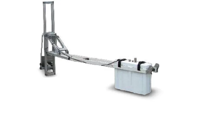
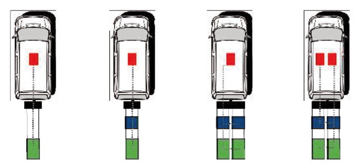
HR1000 and HR2000 horn antennas acquire data without touching the surface. The technical datasheet also lists the TR600 dipole antenna and Dual F 400-900 dual-frequency antenna. Frequency selection should follow the required resolution and investigation objective, rather than the channel count alone.
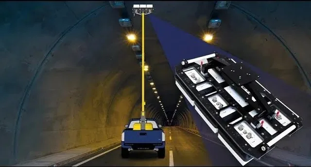
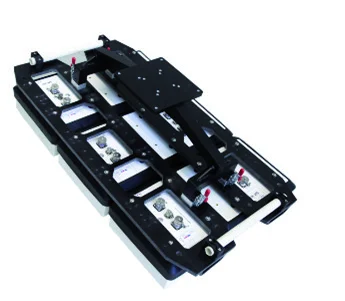
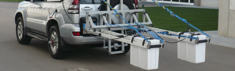
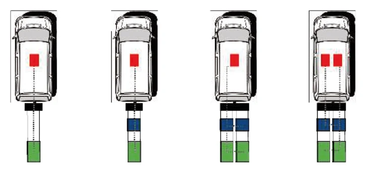
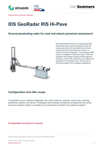
The manufacturer diagram shows alternative antenna and control-unit arrangements. It is not an equipment list for a single package. We establish the required array, mounting geometry and vehicle integration when preparing the quotation.
- HR1000: 1000 MHz; HR2000: 2000 MHz.
- TR600: 600 MHz; Dual F 400-900: 400/900 MHz.
- Up to six channels in the configuration described by the datasheet.
Survey route, positioning and acquisition control
Each profile needs a reliable link to its survey location. RIS Hi-Pave supports a measuring wheel and/or GPS interface, while manufacturer material describes NMEA positioning. Distance recording, the receiver and required connections are confirmed when the system is configured.
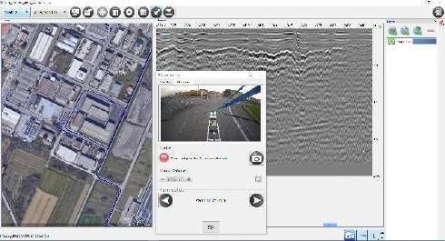
An optional camera allows video to be associated with radar data. The maximum acquisition parameter of 250 km/h is specified at 10 scans/m and 512 samples. The actual survey speed must reflect the configuration, survey geometry, traffic arrangements and working conditions.
- Agree the recording interval along the route.
- Check the association between radargram and position.
- Camera and positioning equipment as defined in the quotation.
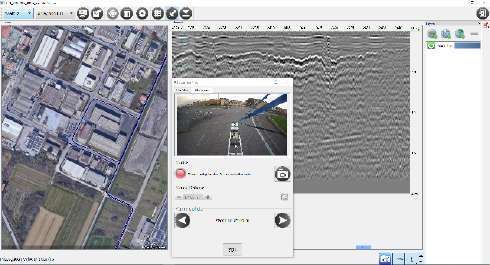
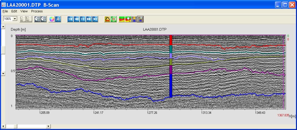
Clear layer boundaries in GRED software
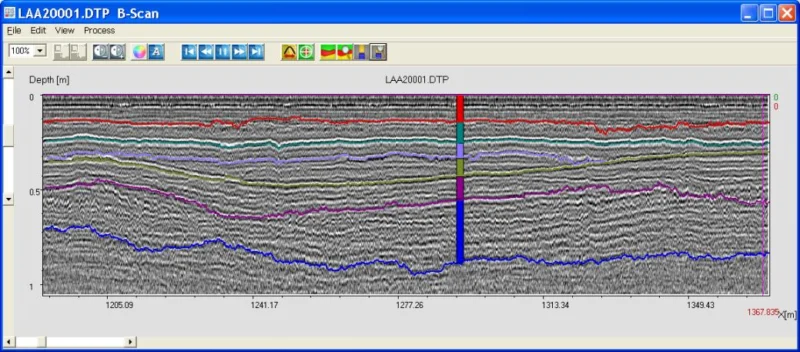
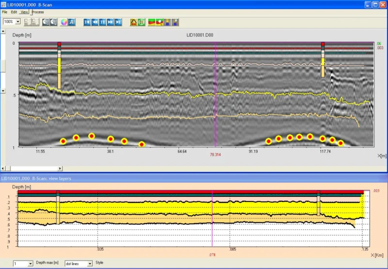
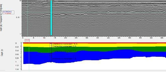
Interpretation starts with data quality and identifying reflections that can be followed consistently along a profile. The GRED 3D tools listed in the manufacturer datasheet include manual and automatic layer tracking, B-scan and C-scan views, filters and 3D presentation.
Automatic tracking can speed up processing, but needs checking where materials change or interference and weak contrast affect the data.
- Compare adjacent radargrams and interpreted layer boundaries.
- Select processing settings for the data and investigation question.
- Have automatic results reviewed by the interpreter.
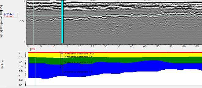
Relate layer thickness to core information
Radar records a wave response, so converting time to depth requires an appropriate propagation-velocity model. Core information helps relate interpreted boundaries to the actual pavement structure and check thickness estimates.
GRED 3D supports core-data input and propagation-velocity estimation. When comparing findings with design records, distinguish well-calibrated areas from locations requiring further investigation. This helps communicate the results together with the limits of confidence in the interpretation.
- Reference radargrams to available core information.
- Assess layer changes between control points.
- Select locations for supplementary investigation.
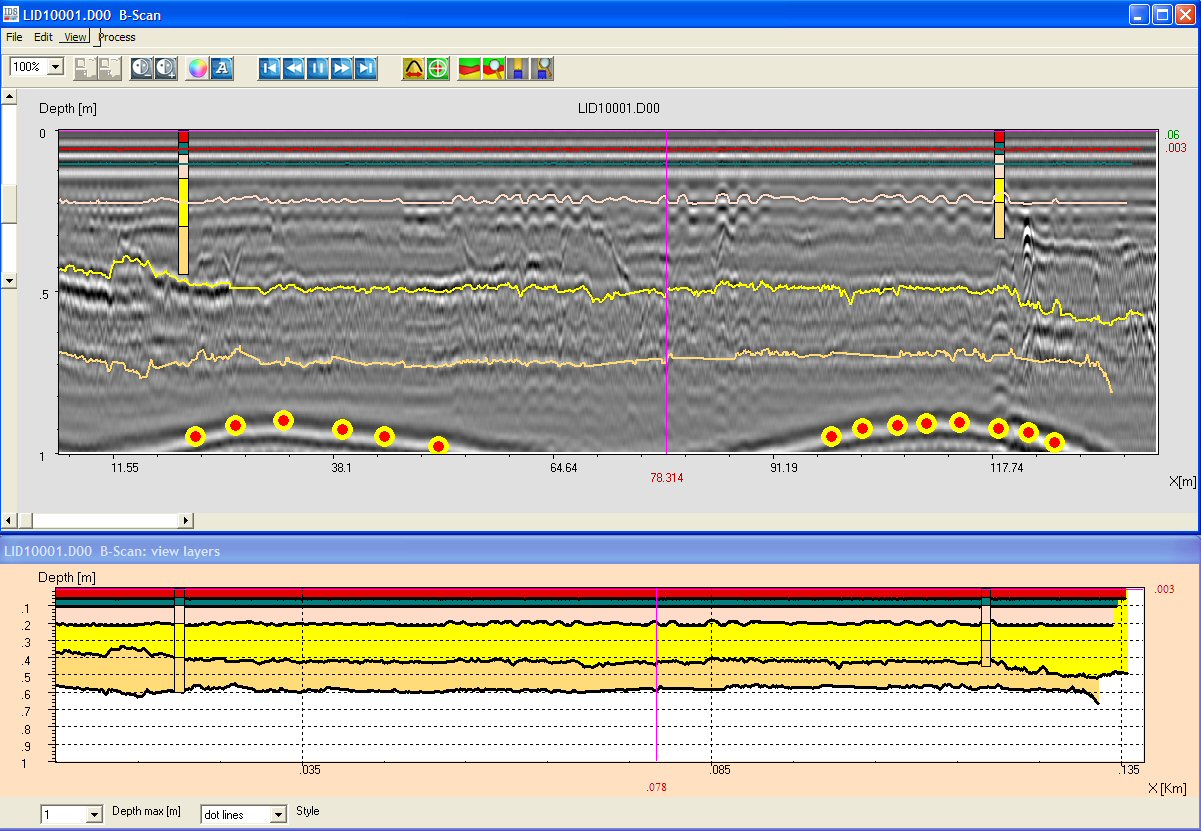
Anomalies, moisture and structural discontinuities
A change in a boundary, reflection character or response across successive profiles may identify an area needing attention. IDS GeoRadar lists voids, delamination and water-saturated areas among the system applications.
The result should not be reduced to an automatic defect label. Interpretation is considered alongside pavement construction, surface condition, records and control data. GPR helps select locations and the scope of further testing; the final engineering diagnosis requires specialist assessment.
- Analyse changes in the context of the entire section.
- Relate the layer profile to observation locations.
- Distinguish a radar indication from a confirmed defect.
Results for documentation and work planning
The deliverable should clearly show the survey route, adopted interpretation and locations requiring verification. The manufacturer datasheet lists export to Excel, ASCII, HDF5, JPG and BMP. The final data-delivery format and licence scope are agreed for the selected configuration.
When requesting a quotation, explain whether the priority is acceptance testing, comparing sections, layer assessment or planning refurbishment. This helps match equipment and processing to the decisions the investigation is intended to support.
- Profiles and layer summaries with interpretation notes.
- Clear identification of further investigation locations.
- An agreed scope for the exported data.
RIS Hi-Pave technical specifications
Values follow the manufacturer datasheet. The final configuration, component compatibility and supplied equipment are confirmed in an individual quotation.
| Parameter | Value |
|---|---|
| Data logger | Panasonic CF-19 or Windows PC with Ethernet LAN; current computer to be agreed |
| Control: standard configuration | 1 × DAD MCh Fast Wave |
| Control: fast configuration | 2 × DAD MCh Fast Wave + Synchro Unit |
| Maximum number of channels | Up to 6, for the configuration in the manufacturer datasheet |
| Air-launched horn antennas | HR1000: 1000 MHz; HR2000: 2000 MHz |
| Other antennas described in the datasheet | TR600: 600 MHz; Dual F 400-900: 400/900 MHz |
| HR1000 or HR2000 antenna weight | 6.5 kg |
| TR600 antenna weight | 3 kg |
| Horn antenna dimensions (L × W × H) | 53 × 23 × 50 cm |
| Dipole antenna dimensions (L × W × H) | 20 × 26 × 20 cm |
| Distance and position recording | Measuring wheel and/or GPS interface; NMEA |
| Maximum acquisition speed | Up to 250 km/h at 10 scans/m and 512 samples; configuration-dependent |
| Protection rating stated in the datasheet | IP65 |
| Video recording | Synchronized radar and video data; camera equipment to be agreed |
| Processing software in the manufacturer datasheet | GRED 3D; licence scope to be agreed |
| Selected interpretation tools | Manual/automatic layer tracking, core input, propagation-velocity estimation |
| Export formats stated in the datasheet | Excel, ASCII, HDF5, JPG, BMP |
Configuration and equipment agreed individually
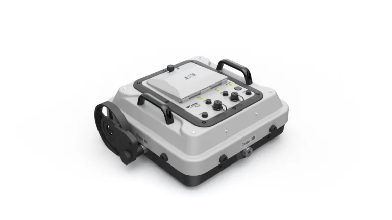
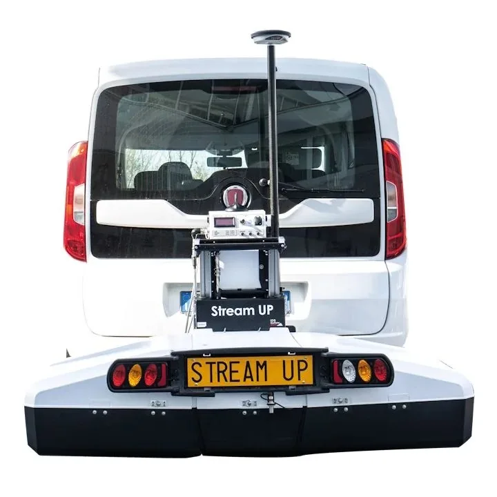
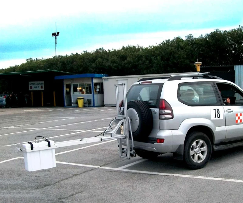
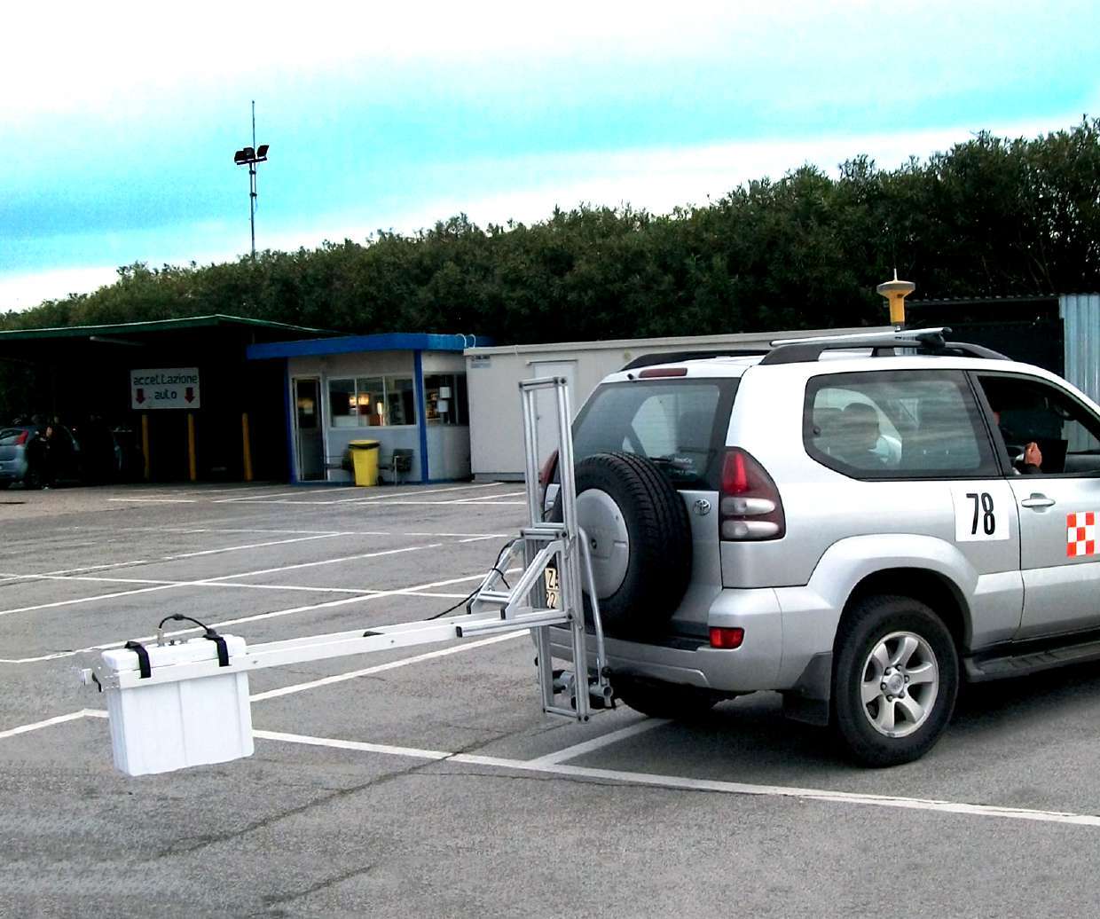
The quotation covers a defined configuration. We confirm antennas, channels, control units, mounting, positioning, computer and licences. Photographs show example manufacturer arrangements; the vehicle and every accessory visible in an image are not automatically included in the supplied equipment.
- Antenna arrangement and frequencies matched to the investigation.
- One or two DAD MCh Fast Wave units; synchronization in the fast configuration.
- Vehicle mounting, measuring wheel, GPS, camera, computer and licences as quoted.
Brochure and datasheet
Explore applications, antenna configurations and system parameters in the downloadable documents.
Questions about RIS Hi-Pave pavement GPR
Is the system suitable for airport pavements?
Yes. The manufacturer identifies runway assessment as a RIS Hi-Pave application. Configuration and survey planning depend on the pavement type, investigation objective and site-access conditions.
Are all antennas and the vehicle included?
No. RIS Hi-Pave is configured for the task. Manufacturer photographs and diagrams show different possibilities. The individual quotation defines the exact antennas, controllers, mounting, software and other equipment.
Does 250 km/h mean the recommended survey speed?
No. It is the maximum acquisition parameter in the manufacturer datasheet, specified at 10 scans/m and 512 samples. It is not a driving recommendation. Survey speed also depends on configuration, required data quality, traffic and operating conditions.
Does GPR provide thickness without calibration?
Converting propagation time to thickness requires an appropriate material model. The software supports velocity estimation and core-data input. Control points help validate the interpretation and assess its reliability.
What information is needed for a quotation?
Describe the pavement and site, investigation objectives, typical route lengths, available vehicle and expected deliverables. Include any requirements for antennas, GPS or software in the enquiry.
GPR survey and data-processing training
We supply equipment and help plan its introduction into daily work. Explore training in GPR surveys, interpretation and software. The programme and arrangements are agreed individually.
Explore trainingConfigure RIS Hi-Pave for your survey
Tell us the pavement type, investigation objectives, route lengths and available vehicle. We will propose a configuration and prepare an individual quotation.
Request a quotation